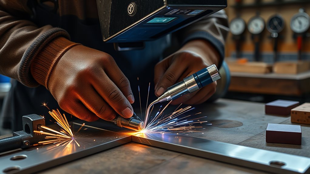
You can reduce welding distortion, rework, and filler waste by controlling heat input, right-sizing welds, and sequencing welds symmetrically around the neutral axis. Use intermittent welds, backstep patterns, fewer qualified passes, correctly matched electrode size, and consistent arc length, travel angle, and travel speed to reduce shrinkage. Strong jigs, accurate presetting, clamps placed against shrinkage forces, and controlled cooling methods can also help keep the weldment dimensionally stable. Always follow a documented welding procedure specification, approved drawings, and qualified operator practices before changing weld size, sequence, or parameters.
Quick Answer
To minimize welding distortion, reduce total heat input, avoid overwelding, balance welds around the neutral axis, use intermittent or backstep sequences where allowed, and hold the work with accurate fixtures. The best results come from combining good joint design, controlled welding parameters, smart sequencing, and inspection after each critical weld stage.
Key Takeaways
- Most welding distortion comes from uneven heating, cooling, and restrained shrinkage.
- Right-sized welds reduce shrinkage force, filler waste, heat input, and cleanup time.
- Intermittent, skip, and backstep welding can control heat buildup when the joint design allows them.
- Balanced weld sequencing around the neutral axis helps prevent bending, twisting, and angular distortion.
- Jigs, clamps, strongbacks, presetting, and inspection checkpoints are essential for repeatable dimensional control.
At a Glance
| Best For | Fabricators, welders, inspectors, and shop teams trying to reduce warping, rework, and dimensional errors. |
| Main Goal | Limit shrinkage forces by controlling heat, weld size, weld order, restraint, and cooling. |
| Tools Needed | Approved WPS, drawings, clamps, strongbacks, fixtures, measuring tools, temperature controls, and inspection records. |
| Difficulty | Moderate to advanced, depending on material thickness, joint design, tolerance requirements, and code rules. |
What Is Welding Distortion and Why It Happens
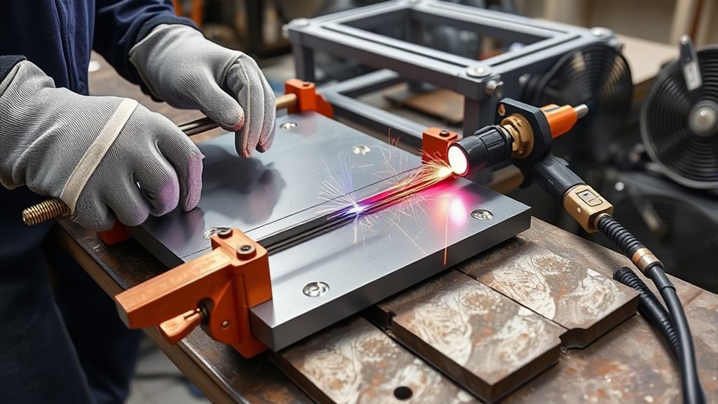
Because welding heats and cools metal unevenly, distortion happens when expansion and contraction are restrained. The weld area expands while hot, then contracts as it cools. If that contraction is uneven or locked in place by surrounding material, clamps, or joint geometry, the weldment can bend, twist, pull out of square, or lose dimensional integrity.
You’ll recognize welding distortion as a dimensional change caused by thermal expansion and contraction of the weld metal and base metal. The arc’s heat causes local expansion, and contraction during cooling creates shrinkage forces. When those forces are not balanced, the part moves.
Common forms include angular distortion, longitudinal shrinkage, transverse shrinkage, bowing, buckling, and twisting. Thin sheet and long unsupported members are especially sensitive because they have less stiffness to resist movement.
Apply controlled welding techniques to manage heat input, bead placement, and sequence. The goal is not only to make a sound weld, but also to make the weld in a way that does not overload the part with unnecessary heat and unbalanced shrinkage.
Use intermittent welds and planned stitch patterns only when the design permits them. In some non-continuous applications, they can sharply reduce weld metal volume, heat transfer, and distortion risk while still meeting strength requirements.
Position welds near the neutral axis where possible and plan sequencing to balance forces. A weld far from the neutral axis has more leverage to bend the part, so weld placement matters as much as weld size.
Inspect dimensions against drawings, tolerances, and applicable standards throughout the job. Distortion is easier to prevent early than to correct after all welds are complete.
Warning: Do not reduce weld size, change weld length, skip welds, peen beads, or alter heat treatment unless the drawing, code, engineer, or approved WPS allows it. Distortion control must never come at the cost of weld strength or safety.
How to Reduce Welding Distortion by Right-Sizing Your Welds
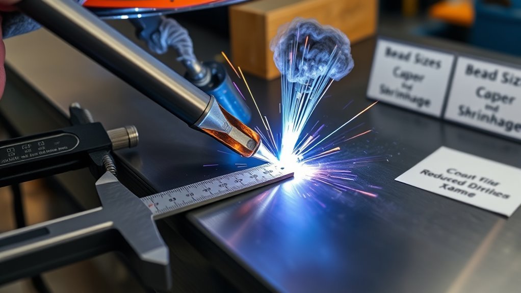
When you size welds to the joint’s load and geometry, you cut shrinkage forces and lower the risk of distortion without sacrificing strength. Oversized welds add extra filler metal, extra heat, extra cooling time, and extra contraction.
You match weld size to the required throat, leg size, joint type, and load case to avoid overwelding and preserve material efficiency. A larger weld is not automatically better. If the design only needs a smaller qualified weld, adding more weld metal may only create more distortion and grinding work.
For thicker plates, beveling or otherwise preparing the joint correctly can improve access and fusion while reducing unnecessary filler volume. Joint preparation should follow the approved procedure, material thickness, weld process, and inspection requirements.
Use fewer, properly controlled passes when appropriate to limit cumulative shrinkage from repeated thermal cycles. Each extra pass reheats the joint and adds another contraction cycle, so pass count matters.
Intermittent and Backstep Welding Techniques
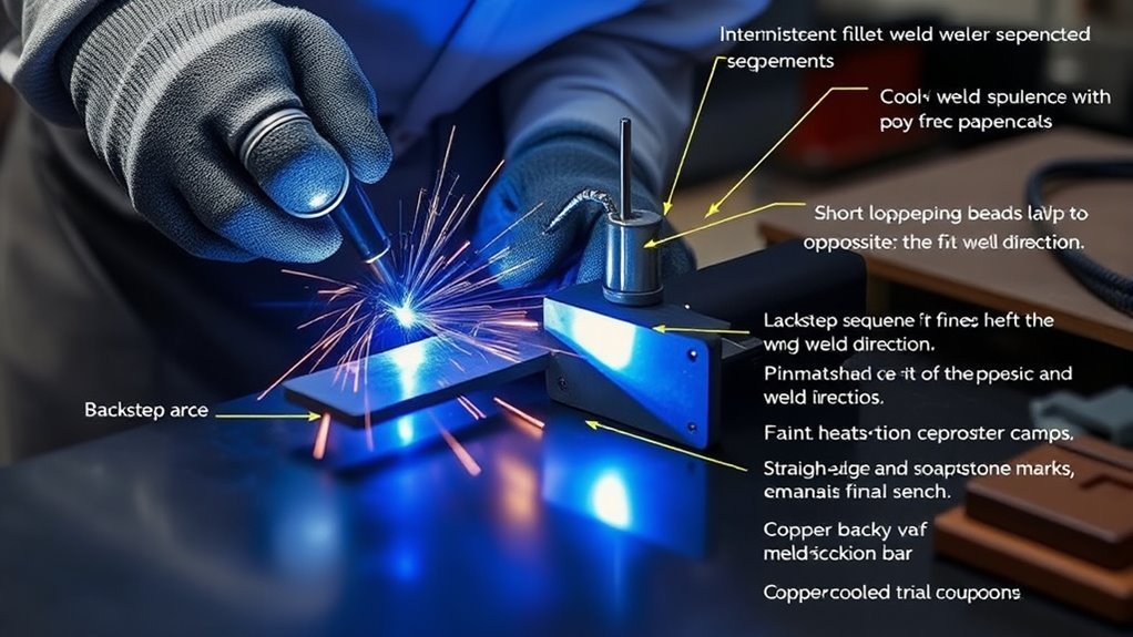
Although you’ll usually use continuous beads for full-strength or sealed joints, intermittent and backstep techniques let you cut heat input and weld metal where continuous welding is not required. These methods are especially useful on long seams, frames, sheet assemblies, brackets, and non-pressure applications where the design allows stitch or skip welds.
Intermittent welding spaces welds along the joint to control shrinkage and reduce metal usage. Instead of one long heat-heavy bead, you place shorter welds at specified lengths and pitch. This can reduce total heat input and lower the chance of bowing or oil-canning.
Backstep welding sequences short beads in a direction opposite the overall weld progression. For example, the job may progress left to right, while each short bead is deposited right to left. This helps distribute heat and shrinkage more evenly along the joint.
You’ll apply intermittent welding when continuous welds are unnecessary. Specify weld length, pitch, end returns, and location so the finished joint still meets code, drawing, and structural requirements.
Use backstep welding to sequence short beads opposite the overall travel direction so heat flow counteracts distortion. This method can help keep plates aligned, especially when combined with tack welds, clamps, and alternating sides.
Both methods demand documented procedures, qualified operators, and inspection criteria to guarantee strength, alignment, and minimized warpage.
Pro Tip: Mark the weld sequence directly on the workpiece or traveler before welding. A simple numbered sequence helps the welder avoid accidentally concentrating too much heat in one area.
Planning Weld Sequence and Balancing Around the Neutral Axis
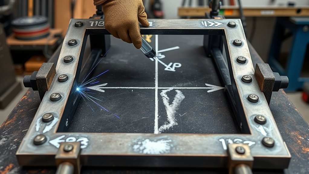
Balance around the neutral axis to offset thermal forces and preserve alignment. If one side receives all the heat and weld metal first, that side will usually pull harder during cooling.
Use intermittent welds strategically to limit heat input and material use while maintaining equilibrium. Follow code-based tolerances and document sequence steps so the same result can be repeated on future parts.
- Alternate welds left and right of the neutral axis to neutralize bending moments.
- Sequence from stiff, central members outward when that helps control restraint.
- Insert short intermittent welds where full seams are not required.
- Verify alignment after each critical pass and adjust sequence as needed.
A good sequence also considers access, tack weld location, fit-up, part stiffness, and inspection timing. The best sequence is the one that produces a sound weld and keeps the part within tolerance without forcing excessive straightening afterward.
Minimizing Number of Weld Passes and Optimizing Electrode Size
You should plan for fewer, properly controlled weld passes when the procedure and joint design allow it. Fewer thermal cycles can reduce cumulative shrinkage and simplify heat control.
Match electrode diameter, filler metal size, wire feed settings, and process parameters to joint geometry and material thickness so each pass achieves proper fusion without over-welding.
Where code and fit-up allow, use efficient pass planning for sections over 0.25 in to maintain strength and reduce defect risk. The goal is not simply to make the largest possible bead, but to deposit the right bead with the least unnecessary heat.
Fewer, Larger Passes
When you reduce the number of weld passes and choose an electrode or wire size suited to the joint, you can cut cumulative shrinkage and lower distortion risk while maintaining required deposit properties. A practical planning target is to avoid needless extra passes while still meeting penetration, bead shape, and inspection requirements.
You’ll optimize pass selection to balance heat input, deposition rate, and mechanical properties. Proper pass planning preserves weld quality and lowers rework because the part receives less repeated heating and cooling.
Use procedure qualification to validate single-pass strength, heat-affected zone control, and defect absence. Do not assume fewer passes are acceptable unless the weld still meets the required standard.
- Larger electrode or wire size can reduce pass count, shorten cycle time, and lower repeated heat cycles.
- Fewer passes can limit cumulative distortion and simplify fixturing.
- Controlled pass planning can improve bead appearance and reduce cleanup.
- Verify parameters per code, WPS, and inspection requirements for traceability.
Match Electrode Diameter
Match electrode diameter to material thickness so each bead achieves proper penetration and deposition in as few passes as practical.
You’ll apply the common shop rule of thumb that many stick welding setups start near 1 amp per 0.001 inch of electrode diameter, then adjust within the electrode manufacturer’s recommended range, the welding position, joint fit-up, and WPS limits.
For materials over 1/4 inch, larger diameters such as 3/32 inch or 1/8 inch may increase penetration and deposition rate, but they must still match position, access, joint prep, and heat input limits.
Fewer passes can lower cumulative shrinkage and distortion. You’ll document parameters to meet code and repeatability.
Verify material compatibility, including coating, alloy, strength level, and joint geometry, before sizing electrodes. Optimize travel speed and angle to match diameter, then confirm fusion with inspection.
This disciplined approach saves time, reduces consumables, and preserves weld integrity.
Single-Pass Techniques
Because single-pass techniques can cut cumulative heat input and shrinkage, adopt them wherever joint design, material thickness, process capability, and acceptance criteria allow. Single-pass welding can help preserve fit-up and dimensional tolerances, but it must still produce complete fusion and a sound bead profile.
You’ll get single-pass benefits such as reduced distortion, faster cycle time, and more consistent metallurgy in suitable applications. Choose electrode size and current based on the manufacturer’s range, WPS, and the penetration needed in one pass.
Train operators to control travel speed, arc length, work angle, and heat input so a single bead achieves full fusion without undercut, overlap, porosity, or lack of fusion.
- Use suitable electrodes or wire sizes to decrease pass count and cumulative shrinkage.
- Verify amperage, voltage, wire feed speed, or electrode settings for expected penetration and bead profile.
- Monitor preheat and interpass temperature even when single-pass welding is planned.
- Practice consistent technique to improve bead appearance and mechanical properties.
Note: A smaller weld made correctly is usually better than an oversized weld that adds heat, shrinkage, and grinding. Always let the drawing, WPS, and design requirements control final weld size.
Presetting, Clamping, and Using Jigs to Hold Alignment
You should preset parts, such as by prebending or prespringing, so shrinkage forces are countered and final geometry meets tolerances.
Clamp components securely before welding and use strongbacks, hard stops, or fixed stops to keep joint alignment stable during all passes.
Where heat input is critical, employ water-cooled jigs or other controlled heat sinks to extract thermal energy and maintain dimensional control throughout the weld cycle.
Preset for Counter-Shrinkage
When you pre-bend or prespring parts to offset expected contraction, clamp them in purpose-built jigs so the assembly stays within tolerances as weld heat is applied and withdrawn.
You’ll use preset techniques for precise shrinkage management: measure anticipated contraction, apply calculated prebend, and secure components in fixtures that locate datum points rigidly.
Trial welds validate preset amounts and reveal needed adjustments. Use jigs that provide thermal control, including water-cooled fixtures where needed, to remove heat and stabilize geometry.
Document preset values and fixture settings for repeatability. Follow weld procedure specifications and tolerance requirements; record deviations and corrective presets.
- Prebend or prespring parts to counter predicted linear or angular shrinkage.
- Use datum-based jigs to lock critical alignment.
- Run trial welds when tolerances are tight or production repeatability matters.
- Use thermal jigs, including water-cooled fixtures where appropriate, to reduce distortion.
Clamp Before Welding
Clamp the assembly in its jig before striking the first tack to lock datum points and neutralize thermal movement during welding.
You’ll select clamp types based on fixture geometry, load direction, access, and material thickness. C-clamps are useful for simple holds, toggle clamps improve repeatability, and magnetic or strap clamps may help with thin sections when they do not interfere with arc stability or safety.
Position clamps to oppose anticipated shrinkage vectors and minimize lever arms that produce distortion. Use progressive clamping techniques, such as pre-tensioning, tack-welding, checking alignment, and retightening, to maintain alignment as heat cycles.
Design jigs to register primary datums and allow access for welding sequence control. Inspect for slippage after each pass and document clamp locations and torque values where the procedure requires them.
Proper clamping techniques reduce post-weld distortion and preserve weldment integrity.
Use Water-Cooled Jigs
After securing the assembly in its jig, consider water-cooled jigs to actively remove heat from the welding area and hold alignment under thermal load. You’ll control thermal management by routing water circulation through channels that contact fixture surfaces, extracting heat and minimizing distortion.
Clamp-to-jig interfaces must be rigid, repeatable, and referenced to datum points so parts cannot shift during welding. Implement monitoring for inlet and outlet temperature and flow to enforce standards and verify consistent cooling performance.
- Design channels to maximize surface contact and uniform water circulation.
- Use hard stops and repeatable clamps tied to inspection datums.
- Verify flow rates and temperature change to confirm thermal management targets.
- Document procedures for setup, purging, and leak testing before welding.
Stress Relief, Peening, and Thermal Control Methods
Although you’ll rely primarily on sound welding technique to limit distortion, targeted stress-relief practices such as controlled peening and thermal stress relief are useful tools for managing residual stresses and shrinkage forces in critical weldments.
You’ll apply peening techniques by systematically striking the bead to stretch and thin the weld surface slightly, reducing localized stress concentration and minimizing distortion. However, peening must be controlled and procedure-approved.
Avoid peening root beads, final passes, thin or crack-sensitive materials, and applications where the WPS or code does not allow it. Poor peening can create surface damage, hidden cracking, or unacceptable work hardening.
For thermal relief, you’ll use controlled heating to an appropriate temperature, hold for the required time to permit stress redistribution, and cool gradually per material-specific procedures. This can improve alignment, lower residual stress, and support predictable mechanical performance.
Both methods address shrinkage forces; you’ll select and document processes per applicable codes, engineering requirements, and material specifications.
Practical Tips for Arc Length, Travel Angle, and Current Settings
When you control arc length, travel angle, and current precisely, you’ll prevent common defects and produce more consistent, code-compliant welds. Stable technique also helps reduce distortion because it avoids erratic heat input.
For shielded metal arc welding, a common starting point is to maintain an arc length close to the electrode diameter, then adjust to the electrode type, position, and puddle behavior. A long arc can increase spatter, instability, and heat spread. An arc that is too short can cause sticking and poor bead shape.
Current settings should stay within the electrode or wire manufacturer’s recommended range and the approved WPS. Too much current increases heat input and undercut risk, while too little current can cause lack of fusion and poor penetration.
Apply a controlled drag or push angle based on process, position, and joint type. For many stick welding flat and overhead applications, a 0–15 degree drag angle can help control the puddle, but the correct angle depends on the process and WPS.
- Keep arc length steady to avoid erratic arcs and inconsistent bead appearance.
- Set amperage, voltage, and wire feed speed within approved ranges for proper fusion.
- Use a controlled travel angle that keeps the puddle stable and the bead profile correct.
- Limit excessive weaving because wide weaves add heat and can increase distortion.
- Keep travel speed consistent so the weld does not become too cold, too convex, overheated, or undercut.
Common Mistakes That Increase Welding Distortion
Many distortion problems come from small decisions repeated across a job. If you correct these mistakes early, you can reduce rework before the weldment moves too far out of tolerance.
- Overwelding: Adding more weld metal than required increases heat, shrinkage, and grinding time.
- Poor fit-up: Large gaps require more filler metal and create uneven shrinkage.
- Welding too much on one side: Concentrating heat on one side pulls the part out of alignment.
- Skipping tacks or using weak tacks: Poor tack welds allow the joint to move before the main weld is complete.
- Ignoring interpass temperature: Excessive heat buildup can worsen distortion and affect metallurgy.
- Removing clamps too soon: Parts can spring or pull after restraint is released.
- No inspection checkpoints: Waiting until the end makes distortion harder and more expensive to correct.
Inspection and Correction After Welding
Even with good planning, you should inspect the weldment during and after welding. Check critical dimensions after tack-up, after the first major welds, after balanced weld groups, and after final cooling.
Use straightedges, squares, calipers, height gauges, templates, or coordinate measuring tools depending on the tolerance level. Record the measurements when repeatability matters, especially for production fixtures and code-controlled work.
If distortion appears early, adjust the remaining sequence, add temporary restraint, allow controlled cooling, or consult the responsible welding engineer before forcing the part back into shape.
Correction methods can include mechanical straightening, heat straightening, stress relief, machining allowance, or controlled rework. These methods must be approved for the material and application because aggressive correction can damage the weldment or change its properties.
How Distortion Control Affects Welding Cost
Distortion costs money through rework, straightening labor, extra filler and grinding, scrapped parts, and the fixtures needed to hold alignment. When you estimate a job, list fixturing, straightening and rework as their own lines instead of hiding them in a general allowance. Our welding cost calculation guide and welding cost estimation workflow show where those lines belong, and the welding job cost guide shows how they affect typical quotes.
Frequently Asked Questions
How do different filler metals affect distortion?
Different filler metals can change heat input, deposition rate, strength, cooling behavior, and solidification shrinkage. Select filler metal based on the base material, joint design, service conditions, and approved procedure. The right filler can help control distortion, but it must still meet strength and compatibility requirements.
Can welding sequence change metallurgical properties?
Yes. Welding sequence can change thermal cycles, cooling rates, heat-affected zone behavior, residual stress, and phase transformation patterns. That is why weld order should follow the WPS, material requirements, and engineering controls instead of being chosen only for convenience.
How does preheating alter residual stress patterns?
Preheating reduces steep thermal gradients and slows the cooling rate. This can lower hardening risk, reduce cracking sensitivity in some materials, improve hydrogen control, and help residual stresses distribute more gradually. Preheat temperature must match the material, thickness, filler metal, and WPS.
When is vibration stress relief preferable to thermal methods?
Vibration stress relief may be considered when a large or complex assembly cannot be heat treated easily, when thermal distortion must be avoided, or when dimensional stability is the main concern. It should be evaluated against project specifications because it is not a universal replacement for thermal stress relief.
Do shielding gas choices influence shrinkage?
Yes. Shielding gas composition can affect arc stability, penetration profile, bead shape, spatter, heat input, and cooling behavior. Gas flow rate also matters because poor shielding can create defects that require rework, adding more heat and more distortion risk.
What is the fastest way to reduce distortion on thin metal?
Use short welds, skip around the joint, let heat spread evenly, clamp the part firmly, and avoid overwelding. Thin metal moves quickly, so tack spacing, heat control, and travel speed are more important than trying to correct the part after it warps.
Should clamps always be tighter to prevent distortion?
No. Clamps should be strong and correctly placed, but excessive restraint can lock in stress or cause cracking in some situations. Use clamps, strongbacks, and fixtures according to the joint design, material behavior, and welding procedure.
Sources
- OSHA Welding, Cutting, and Brazing — general safety practices for welding work.
- American Welding Society Standards — welding standards and procedure guidance.
- Lincoln Electric Welding Resource Center — welding technique, filler metal, and process education.
- TWI: Distortion in Welding — explanation of weld distortion causes and control methods.
Conclusion
You’ve got the main tools and techniques to cut distortion: right-size welds, plan sequences around the neutral axis, use intermittent or backstep patterns where allowed, and minimize passes with proper electrode sizing. Clamp, jig, and preset fixtures to hold alignment, then control heat with sound technique, measured thermal cycles, stress relief, and procedure-approved peening when appropriate. Dial in arc length, travel angle, current, and travel speed according to the WPS. Follow these standards-driven steps consistently to produce predictable, repeatable, and dimensionally stable welds.