Inertia friction welding cost savings on suitable industrial rollers come from joining separately sized journals, tubes, hubs, or sleeves instead of machining the entire assembly from oversized stock. The largest savings usually come from lower raw-material use, less turning, faster assembly, and strategic use of dissimilar metals. Results are application-specific, however, and must be confirmed through design review, welding trials, qualification testing, and a complete cost comparison.
Quick Answer
Inertia friction welding may lower roller costs when it replaces heavily machined billets or multi-step welded assemblies with near-net components. A supplier case study quoted one OEM’s estimate of 40–70% material loss in its former machining route and an assembly time falling from about 15 minutes to about 2 minutes per roller. Those are one customer’s estimates and are not universal.
Key Takeaways
- Inertia friction welding is a solid-state rotary process that normally requires no filler metal, flux, or shielding gas.
- The strongest business case occurs when near-net journals or hubs replace large amounts of purchased stock and CNC machining.
- Savings percentages must be calculated from the existing roller design, annual volume, alloy prices, tooling, inspection, logistics, and finishing requirements.
- Dissimilar metals can provide cost and weight advantages, but every pairing requires metallurgical review and qualification.
- Machine guarding, stored-energy control, procedure qualification, production monitoring, and part-specific inspection are essential.
What Is Inertia Friction Welding and Why It Matters for Rollers
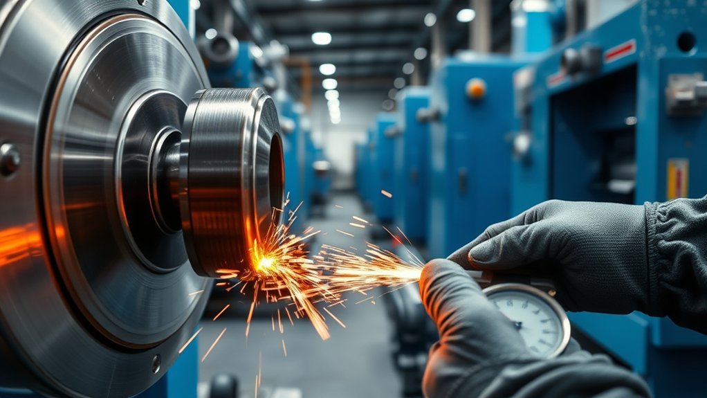
Inertia friction welding, or IFW, is a form of rotary friction welding. One component is attached to a rotating spindle and flywheel, while the other remains stationary. The flywheel is accelerated to a calculated speed, the drive is disconnected, and axial force brings the two joining surfaces together.
Friction converts the flywheel’s stored kinetic energy into heat at the interface. The materials soften and flow without intentionally melting. Continued axial force pushes plasticized material outward as flash and consolidates the interface into a solid-state bond. The process is described in more detail by TWI’s rotary friction-welding guidance.
For roller production, IFW can be valuable because it allows a manufacturer to build a roller from pieces that are already close to their finished diameters. A tube, journal, stub shaft, hub, or wear surface can be selected for its specific function rather than machining every feature from one large piece of expensive stock.
The process normally requires no filler metal, flux, or shielding gas. It is also machine-controlled, making it suitable for repeat production after the equipment and welding procedure have been qualified. That does not mean every weld is automatically defect-free. Joint quality still depends on material condition, geometry, alignment, stored energy, axial force, upset, equipment repeatability, and acceptance testing.
Note: “Solid-state” does not mean the interface remains unchanged. The weld zone experiences intense heat and plastic deformation, which may cause recrystallization, phase transformation, hardness changes, or interfacial-layer formation.
How the Inertia Friction Welding Process Works Step by Step
The IFW sequence is short, but it must be engineered for the exact material combination and part geometry. The principal inputs include rotational speed, flywheel inertia, axial force, joining area, component stick-out, surface condition, and the amount of axial shortening allowed.
Energy and Motion
The rotating assembly stores kinetic energy according to its moment of inertia and rotational speed. The machine accelerates the flywheel and rotating workpiece to a specified speed. Once that speed is reached, the drive is disengaged and the flywheel begins to coast.
The stationary component is advanced into the rotating component under controlled axial force. Friction at the joining faces generates localized heat. The interface softens, and material begins to move radially outward.
As the flywheel slows, its stored energy is consumed by friction, machine losses, heating, and deformation. The spindle eventually reaches zero speed. Axial force is maintained, or controlled according to the qualified process, while the softened interface consolidates.
Published IFW applications commonly complete the active welding event in a few seconds to several tens of seconds. That is not the same as the total machine cycle, which also includes loading, clamping, acceleration, part transfer, flash handling, unloading, and inspection.
Welding Sequence Steps
- Review the materials and geometry. Confirm that at least one component can rotate safely and that the joint can be designed around an axial interface.
- Prepare the joining faces. Follow the qualified requirements for machining, cleaning, flatness, perpendicularity, and contamination control.
- Load and align the components. Clamp each part with enough grip length to resist torque and axial force without damaging critical surfaces.
- Accelerate the rotating assembly. Bring the flywheel and workpiece to the specified rotational speed.
- Disengage the drive and apply axial force. Advance the stationary component into contact with the rotating face.
- Generate heat and upset. Friction softens the interface while axial force displaces material and contaminants toward the flash.
- Consolidate the joint. Maintain the qualified force as rotation stops and the bond forms.
- Unload and inspect. Check upset, axial shortening, flash symmetry, dimensions, runout, parameter records, and required acceptance tests.
- Finish the roller. Remove flash and machine bearing seats, seal surfaces, coating areas, or other features when required by the drawing.
Pro Tip: Record weld-event time and total production-cycle time separately. A fast weld can still have a slow overall cycle if loading, handling, flash removal, or inspection creates a bottleneck.
Material Savings: Reducing Machining Waste
The largest material saving often comes from replacing an oversized billet with several near-net components. Instead of turning a long, large-diameter bar down to create smaller journals, the manufacturer can begin with a tube or roller body and weld correctly sized journals to its ends.
Near-Net Blank Production
A near-net blank is an assembly whose major diameters and lengths are already close to the final drawing. Only the critical surfaces and tolerances need final machining. This approach can reduce:
- Purchased billet weight
- CNC turning time
- Cutting-tool consumption
- Chip handling and recycling
- Machine energy used for bulk stock removal
- Work in progress between separate manufacturing operations
A supplier case study from Enbi Group described an OEM that previously machined roller journals from 4-inch-diameter, 12-inch-long billets. According to that OEM, its former method removed about 40–70% of the billet material, depending on the journal design. The percentage describes material loss in that specific machining route, not a guaranteed IFW saving for every roller.
In one roller-manufacturing case study, the previous billet-turning method removed 40–70% of the starting material. The value of IFW came from redesigning the assembly around near-net pieces, not from the weld alone.
Less Machining Scrap
Material savings should be measured by weight rather than by a broad percentage. For each design, compare the purchased weight of the existing blank with the purchased weight of the proposed IFW components. Then subtract the mass of required flash, cutoff allowances, qualification samples, and final machining stock.
The financial value of reduced scrap is not simply the purchase price of the removed metal. Include the scrap resale credit in the baseline calculation. Expensive alloys, large diameter reductions, long cycle times, and limited machine capacity generally strengthen the case for a near-net design.
IFW does not eliminate machining. Rollers may still require finish turning, grinding, straightening, balancing, coating preparation, bearing-seat machining, or flash removal. The benefit is that machining can focus on functional surfaces instead of removing large amounts of unnecessary stock.
Cutting Cycle Time and Increasing Throughput
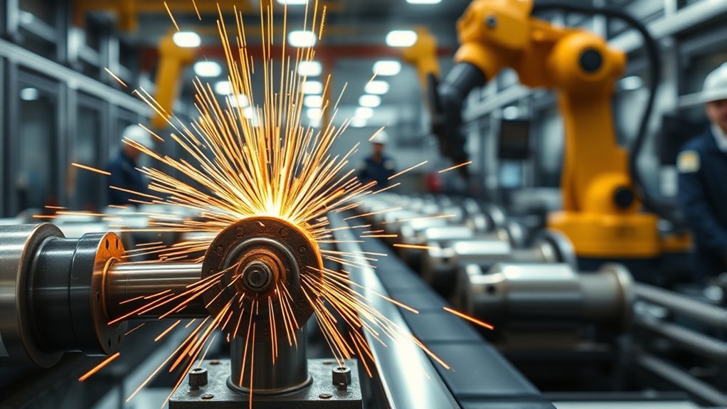
IFW can shorten production when it replaces slow heating, press fitting, fusion welding, long turning cycles, or repeated transfers between suppliers. The improvement must be measured against the complete current route, not against an assumed welding time.
In the Enbi roller case study, the OEM reported that assembling both ends of one roller with its former heating, insertion, and induction-welding method took about 15 minutes. The supplier’s friction-welding process completed both ends in about 2 minutes. This is a valuable commercial example, but it is not a universal IFW cycle specification.
To estimate throughput correctly, create a time study for:
- Material cutting and preparation
- Part loading and clamping
- Flywheel acceleration
- The active welding event
- Unloading and cooling or handling
- Flash removal and finishing
- Dimensional inspection and process-record review
- Part transfer, queue time, and changeovers
Higher throughput is useful only when the surrounding operations can support it. A welding machine that finishes faster than the loading station, lathe, inspection cell, or coating line may simply move the bottleneck elsewhere.
Note: Supplier claims such as “50–60% cycle reduction” or “10 times faster” and the customer’s 15-minute-versus-2-minute example use different comparisons. Validate any cycle-time figure against your own process.
Joining Dissimilar Metals for Lightweight, High-Performance Rollers
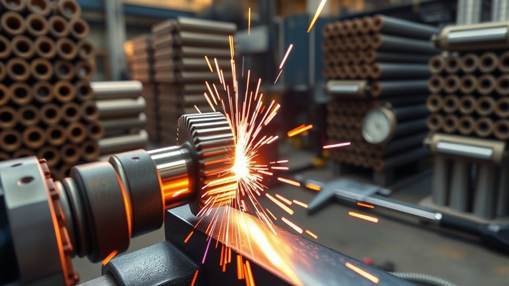
One of IFW’s main design advantages is its ability to join some combinations that are difficult to join by fusion welding. A roller may use a lower-cost body or core with higher-performance material only at journals, bearing seats, wear surfaces, corrosion-exposed areas, or other critical locations.
Possible design goals include:
- Reducing the quantity of stainless steel, tool steel, nickel alloy, or another costly material
- Reducing rotating mass without weakening critical wear or load-bearing areas
- Combining a readily machinable component with a stronger or more wear-resistant component
- Separating functions so each section receives the most suitable heat treatment or surface finish
Dissimilar-metal capability is not unlimited. The two materials may soften and deform at different rates. One side may supply most of the upset while the other moves very little. The interface may also develop brittle compounds, hardness peaks, residual stress, or an undesirable reaction layer.
The engineering review should address:
- High-temperature ductility and plastic-flow compatibility
- Thermal conductivity and heat distribution
- Potential intermetallic formation
- Hardenability and the need for pre-weld or post-weld heat treatment
- Galvanic-corrosion risk in the service environment
- Strength, fatigue, impact, and temperature requirements
- Coating compatibility and exposure of the interface after final machining
Because IFW is a solid-state process, it can reduce melting-related defects and may limit the width of the affected region. It does not preserve the original interface metallurgy unchanged. Research has documented recrystallization, hardness variation, phase transformation, and nanoscale interfacial layers in different IFW material systems.
Quality and Strength: Joint Performance and Repeatability
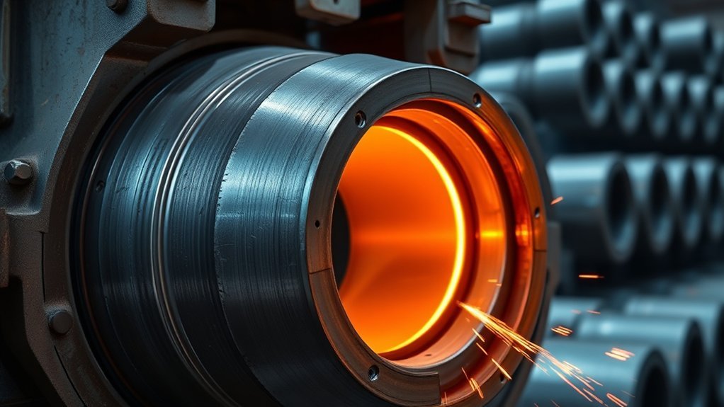
IFW can produce strong, repeatable joints because rotational speed, inertia, axial force, displacement, and timing are controlled by the machine rather than by manual torch movement. The process also avoids filler-metal and shielding-gas variables.
Terms such as “forged-quality” and “100% weld through the contact area” are commonly used by suppliers to describe the continuous annular interface that can be created by a successful rotary friction weld. They should not be interpreted as automatic proof that every production part meets its design requirements.
Qualified Joint Integrity
Joint performance must be demonstrated through a qualified welding procedure. The current AWS C6.2/C6.2M:2021 specification addresses qualification of rotary friction-welding equipment, procedures, and operators. It also addresses destructive and nondestructive examination requirements and weld-parameter reproducibility.
A qualification program may include:
- Material certification and traceability
- Approved joint design and component condition
- Recorded rotational speed, inertia, force, displacement, upset, and cycle data
- Macrosection or metallographic evaluation
- Tensile, bend, torsion, impact, fatigue, or other application-relevant tests
- Hardness mapping across the interface
- Dimensional, runout, straightness, and flash-symmetry checks
- Defined requalification triggers when equipment, geometry, materials, or parameter limits change
ISO 9001:2015 can indicate that a supplier maintains a documented quality-management system. It does not replace a welding procedure specification, procedure qualification record, machine qualification, or part-specific acceptance criteria.
Warning: Do not reduce a roller’s design safety factor solely because an inertia friction weld appears strong. Any design optimization must be supported by qualified joint properties, service loads, fatigue requirements, applicable codes, and approval from the responsible engineer.
Consistent, Repeatable Results
Once the procedure is qualified, production consistency can be supported by monitoring the variables proven to correlate with acceptable welds. Parameter windows should be based on actual qualification data rather than generic machine settings.
| Control | What It Helps Confirm |
|---|---|
| Rotational speed and flywheel setup | The intended stored-energy condition was achieved. |
| Axial-force profile | The interface received the qualified forging load. |
| Upset and axial shortening | Material flowed within the qualified displacement window. |
| Flash appearance and symmetry | Alignment and material flow appear consistent, subject to the approved acceptance criteria. |
| Runout and dimensions | The welded blank can meet final roller geometry after finishing. |
| Recorded cycle signature | The production cycle stayed within the validated process envelope. |
Equipment Capabilities: Welder Sizes and Work Envelopes
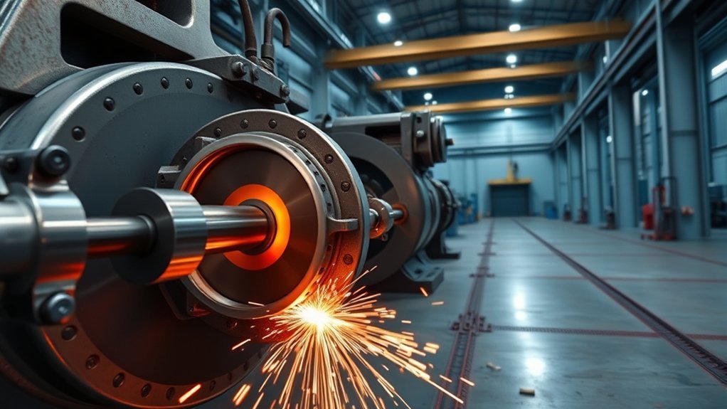
Equipment selection depends on more than the roller’s outside diameter. The machine must provide enough energy, axial force, grip capacity, spindle clearance, component length, and fixturing space for the exact joint.
The following figures describe three MTI-built machines listed by Enbi for its own friction-welding operation. They are useful examples of available work envelopes, but they should not be treated as universal specifications for every machine carrying a similar model designation.
| Machine Listed by Enbi | Listed Bar-Diameter Capacity | Listed Maximum Work Envelope |
|---|---|---|
| Inertia Welder 120 | 0.25–1.2 inches | 3.5 × 21.25 inches |
| Inertia Welder 180BX | 0.5–1.8 inches | 4 × 144 inches |
| Inertia Welder 250B | 1.0–10.0 inches | 10 × 104 inches |
Enbi states that its 180BX has an open-end design that accommodates almost unlimited part length. Actual feasibility still depends on support, alignment, handling, floor layout, and the dimensions of the joint area.
A machine’s nominal diameter range does not confirm that it can weld a particular roller. The supplier must review joining area, material strength, required energy, axial force, grip length, part mass, and tooling access.
Design Information a Welder Needs
Provide the specialist with complete drawings and process requirements, including:
- Material specifications, condition, hardness, and certifications
- Joint location and joining-face dimensions
- Finished roller length and allowable weld shortening
- Maximum runout, straightness, concentricity, and balance requirements
- Grip areas and surfaces that cannot be marked
- Flash-removal and machining allowances
- Heat-treatment sequence
- Surface coatings and corrosion requirements
- Service loads, speed, temperature, fatigue duty, and environment
- Annual volume, batch size, first-article quantity, and production forecast
- Required standards, tests, documentation, and traceability
Inertia Friction Welding Cost: Real-World Roller Savings
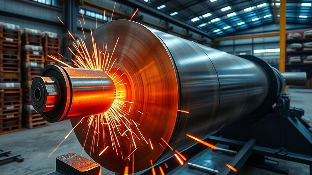
The best-documented savings example is a supplier case study from Enbi, based on an OEM representative’s estimates rather than independently audited measurements. The customer reported three main improvements:
- Its former billet-machining route removed approximately 40–70% of the journal material.
- Its former assembly process took about 15 minutes per roller, while the supplier’s friction-welded assembly took about 2 minutes for both ends.
- The redesigned rollers reduced weight, scrap, and cost while consolidating work that had previously moved between different groups.
These figures show what may be possible when the original design is especially material- and labor-intensive. They should be used as a case-study benchmark, not as a quotation or guaranteed result.
How to Calculate Roller Cost Savings
Build the comparison from the complete cost of one acceptable roller under each manufacturing route.
| Cost Element | Existing Route | Proposed IFW Route |
|---|---|---|
| Purchased material | Oversized billet, tube, journals, filler, or other inputs | Near-net tube, journals, hubs, sleeves, and cutoff allowance |
| Scrap credit | Value recovered from chips and offcuts | Value recovered from flash, offcuts, and finishing stock |
| Machining | Rough and finish turning, tool wear, machine burden, and handling | Joining-face preparation, flash removal, and final machining |
| Joining and assembly | Heating, pressing, fusion welding, filler, gas, straightening, or multiple transfers | IFW machine time, labor, fixture use, and part handling |
| Quality cost | Inspection, rework, rejection, warranty, and documentation | Process monitoring, dimensional checks, NDT where required, and qualification amortization |
| Logistics and inventory | Transfers, supplier minimums, queue time, and work in progress | Shipment to and from the welding supplier or internal cell |
Annual gross savings can be calculated as:
(Existing cost per acceptable roller − IFW cost per acceptable roller) × annual production volume
Then subtract annualized fixture, qualification, maintenance, financing, floor-space, and support costs. For an equipment purchase, a simple payback estimate is:
Total one-time investment ÷ annual net savings
A complete business case should also test lower-volume, expected-volume, and higher-volume scenarios. Include realistic rejection rates, machine utilization, alloy-price changes, and demand variability.
One-Time Costs That Are Easy to Miss
- Design engineering and drawing changes
- Development samples and parameter trials
- Chucks, collets, clamps, supports, and custom fixtures
- Procedure and equipment qualification
- Destructive testing and metallography
- First-article inspection
- Heat-treatment development
- Automation, guarding, utilities, foundation, and installation
- Operator and maintenance training
- Customer approval or regulatory documentation
Limitations and Material Considerations for Roller Applications
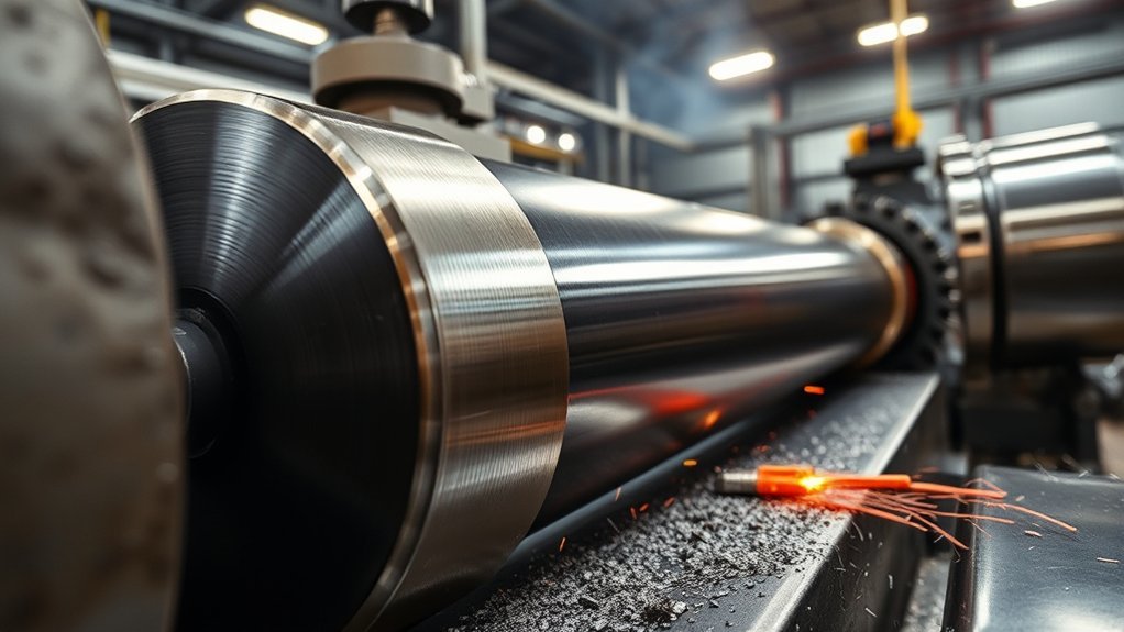
IFW is not suitable for every roller. It generally works best when the joint is rotationally symmetric, one component can rotate, the parts can be clamped securely, and the interface can be loaded axially.
Potential limitations include:
- Non-axisymmetric geometry: Angled joints, interrupted interfaces, or components that cannot rotate may require another joining process or a redesigned subassembly.
- Insufficient grip area: Thin, delicate, coated, or finish-critical components may be difficult to clamp without distortion or marking.
- Unequal deformation: Large differences in material strength, diameter, or temperature response can cause most of the upset to occur in one component.
- Brittle phases or inclusions: Some cast materials, free-machining alloys, leaded materials, graphite-containing metals, and hardenable steels require careful testing because inclusions or local phases may weaken the interface.
- Interfacial reactions: Dissimilar metals may form brittle compounds or reaction layers even though the bulk materials do not melt.
- Axial shortening: The design must allow for predictable upset and loss of length during welding.
- Flash access: External or internal flash may need removal and must not interfere with bearings, seals, coatings, fluid passages, or service clearances.
- Heat-treatment conflict: A thermal cycle suitable for one material may over-temper, harden, or otherwise harm the other.
- Machine capacity: Diameter alone does not establish feasibility. Required force, energy, component length, mass, and tooling must remain within the machine envelope.
Material screening should not rely on a simple “weldable” or “not weldable” list. Recent research on AISI 1215 free-machining steel, for example, shows that IFW’s high shear can break up and redistribute MnS inclusions differently from continuous-drive friction welding. The practical decision still requires representative trials and mechanical evaluation.
Note: A successful visual weld is not enough to approve a new material combination. Use representative material heats, production dimensions, actual heat treatments, and service-relevant tests during qualification.
When Inertia Friction Welding May Not Be Economical
Another method may cost less when production volume is very low, the current part requires little machining, the material combination demands extensive development, the roller cannot be redesigned around an axial joint, or finishing and inspection remove most of the expected time saving.
Low-volume replacement rollers may be more economical to machine from solid stock because the existing CNC route avoids new fixtures and qualification. IFW becomes more attractive as repeat volume, material cost, billet-to-finished-part weight ratio, and current assembly complexity increase.
Outsourcing Versus Buying Inertia Friction Welding Equipment
A contract friction-welding specialist is often the lower-risk starting point. For machine pricing, see our guides to friction welding machine costs and friction stir welding equipment costs. The supplier already has equipment, operators, maintenance knowledge, tooling experience, and process-development capability. Outsourcing also allows an OEM to validate annual savings before committing to a machine purchase.
| Approach | Advantages | Tradeoffs |
|---|---|---|
| Contract welding | Lower initial capital, access to multiple machines, experienced development support, and easier volume testing | Freight, supplier lead time, scheduling dependence, minimum quantities, and external process control |
| In-house equipment | Direct scheduling, lower transport, process ownership, automation opportunities, and potential savings at sustained high volume | Machine, installation, guarding, utilities, fixtures, maintenance, training, qualification, staffing, and utilization risk |
Before buying a machine, compare the expected annual spindle hours with realistic availability and changeover losses. A technically capable machine can still produce a weak return if the plant cannot keep it loaded with qualified work.
How to Partner With a Friction Welding Specialist for Roller Production
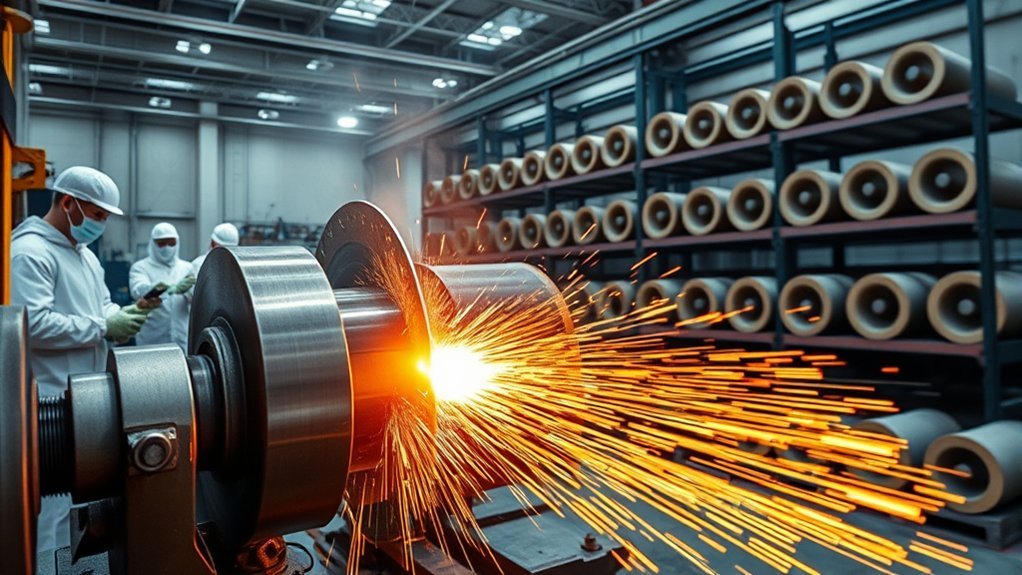
Start the supplier discussion with measurable requirements rather than a general request to “reduce cost.” Provide the current process route, annual volume, purchased material weight, finished weight, cycle times, scrap credit, inspection cost, rejection rate, and logistics cost.
Supplier Evaluation Checklist
- Can the supplier review the complete material specifications and heat-treatment conditions?
- Does an available machine have enough force, energy, grip capacity, and work envelope?
- What similar material combinations and geometries has the supplier qualified?
- Which standard will govern the welding procedure and equipment qualification?
- Which process parameters are recorded for every weld?
- How are upset, flash symmetry, dimensions, runout, and cycle signatures evaluated?
- Which destructive tests and NDT methods will be used during qualification?
- What changes trigger requalification?
- Who owns the fixtures, parameter data, qualification records, and developed process?
- What are the first-article, sample, production, and repeat-order lead times?
- How will nonconforming parts, corrective actions, and traceability be handled?
- Can the supplier quote both prototype and expected production volumes?
Performance Measures for the Project
| Objective | Recommended Measure |
|---|---|
| Material saving | Purchased weight per acceptable finished roller |
| Cycle-time improvement | Total elapsed production minutes per acceptable roller |
| Machining reduction | CNC spindle minutes and tool cost per roller |
| Quality | First-pass yield, qualification results, rejection rate, and dimensional capability |
| Lead time | Order release to accepted delivery, including external processing |
| Financial return | Net annual saving, payback period, and sensitivity to volume and alloy price |
Use pilot runs to compare the proposed roller with the current design. Acceptance criteria should be agreed before production samples are welded. A clear agreement should cover drawings, materials, parameter limits, inspections, documentation, ownership, delivery, corrective action, and change control.
Warning: IFW machinery contains high-speed rotating components, a stored-energy flywheel, powerful hydraulic or mechanical clamping systems, hot flash, pinch points, and heavy workpieces. Use interlocked guarding, verified energy isolation, approved lifting methods, trained operators, and the machine manufacturer’s procedures. OSHA lockout guidance specifically identifies rotating flywheels and hydraulic systems as stored-energy hazards.
Frequently Asked Questions
What safety precautions are unique to inertia friction welding operations?
The main hazards include high-speed rotation, flywheel energy, hydraulic pressure, hot flash, flying particles, crush points, and heavy-part handling. Use interlocked guards, verified zero-energy procedures, lockout/tagout during service, flywheel and spindle inspection, secure clamping, emergency-stop testing, hot-part controls, and manufacturer-approved maintenance procedures. Operators should never bypass guards or enter the danger zone until rotational, hydraulic, electrical, pneumatic, and thermal energy has been made safe.
How does inertia friction welding affect roller surface finish and post-process machining?
IFW creates upset and flash at the joint, so the welded interface normally needs a defined finishing allowance. Depending on the roller, post-weld work may include flash removal, finish turning, grinding, straightening, balancing, coating preparation, and machining of bearing or seal surfaces. Near-net design reduces bulk stock removal but does not guarantee a finished roller directly from the welding machine.
What inspection and nondestructive testing are recommended for welded rollers?
Start with recorded process parameters, visual examination, flash and upset checks, dimensional inspection, runout, straightness, and material traceability. Qualification commonly adds destructive testing and metallography. Dye penetrant, magnetic-particle, ultrasonic, or radiographic examination may be appropriate in some designs, but no single NDT method is best for every IFW joint. The method and acceptance criteria should be selected by qualified personnel under the applicable specification.
Are there long-term fatigue or creep concerns for inertia-welded roller joints?
Yes. A properly qualified IFW joint can have strong fatigue performance, but the result depends on the alloys, interface, weld parameters, hardness profile, residual stress, surface finish, geometry, service load, and environment. Creep becomes important at elevated temperature and sustained stress. Use service-relevant fatigue, temperature, or creep data instead of assuming that all IFW joints behave like the parent metals.
What lead times are typical when outsourcing inertia friction welding?
There is no dependable universal lead-time range. A repeat order using approved tooling may move quickly, while a new material combination can require drawing review, material procurement, fixtures, parameter trials, destructive tests, customer approval, and first-article inspection. Ask the supplier to quote development, first-article, and repeat-production lead times separately.
Does inertia friction welding eliminate all roller machining?
Usually not. It can eliminate much of the rough machining needed to create large diameter changes, but joining faces, flash, journals, bearing seats, seal surfaces, coatings, and precision tolerances may still require machining or grinding. The correct comparison is the total machining time before and after redesign.
How can a manufacturer tell whether IFW will save money?
Compare purchased material weight, scrap credit, machining time, assembly labor, consumables, inspection, rejection, logistics, tooling, qualification, and annual volume for both routes. Then request representative development samples and a production quotation. The strongest candidates usually combine high material removal, costly alloys, repeat volume, and a joint that can be designed around rotational symmetry.
Conclusion
Inertia friction welding can lower roller-manufacturing costs when it enables a genuine near-net redesign. The process may reduce purchased material, rough machining, assembly labor, consumables, supplier transfers, and work in progress. It can also support useful combinations of different metals.
The largest published figures in this article come from one OEM case study whose previous process was especially material- and labor-intensive. Treat those results as evidence of potential, not as guaranteed savings. Build the decision around actual part weights, cycle studies, annual volume, tooling, qualification, finishing, inspection, and logistics.
A successful program requires more than selecting a welding machine. The material combination, joint geometry, upset allowance, flash access, heat treatment, process limits, safety controls, and acceptance tests must all be defined. Start with an engineering review and representative trials, then scale production only after the welded roller meets its mechanical, dimensional, safety, and financial targets.
Sources
- TWI: Rotary Friction Welding — solid-state process fundamentals, advantages, dissimilar-material capability, automation, and consumables.
- AWS C6.2/C6.2M:2021 — rotary friction-welding machine, procedure, operator, examination, and quality-assurance qualification.
- Enbi Inertia Friction Welding Case Study — the roller OEM’s reported material-loss and assembly-time comparison.
- Enbi Friction Welding Services — supplier-reported machine work envelopes and installed equipment capabilities.
- OSHA 29 CFR 1910.212 — machine guarding for rotating parts, points of operation, flying chips, and sparks.
- OSHA 29 CFR 1910.147 — control of hazardous electrical, mechanical, hydraulic, pneumatic, thermal, and stored energy during servicing.